Back to basics: Suspension and steering
In this article: In the first of a multi-part series, we take you back to basics with suspension and steering technologies, with a deep dive into basic system geometry
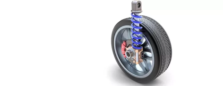
The only connection between the road wheels and the vehicle structure is the suspension system, which has to re-act the drive torque, the braking torque, the forces generated in cornering and the yaw caused by the centre of pressure position relative to the centre of gravity. In addition, all the links must not fail, be produced at minimal cost and be able to sustain a high speed road obstacle impact without braking.
The tyre contact patch should remain in full contact with the road surface at all times, which requires a spring and damper system that allows movement over obstacles but a return to normal ride height as soon as possible. The primary system is the tyre, making the suspension spring and damper secondary. The tyre absorbs minor road imperfections by allowing the tread belt to move via the side wall relative to the road wheel, while the suspension takes up the major road obstacle displacements along with controlling the sprung vehicle mass dynamics.
Geometry
The geometry is carefully developed by ride and handling engineers to make the best possible use of the selected tyres – indeed tyre selection can make quite a difference to vehicle dynamics no matter how humble. The original fitment will have tyre compounds which are formulated for the major destination markets so that the operational temperature range and abrasion resistance reflect the regional environment. The engineers use this behaviour to optimise the position of the road wheel relative to the front and rear of the vehicle to deliver the desired handling characteristics, so the alignment data is specific to the model type as well as the allowable tyre choice for that vehicle. Needless to say part of those values will be the pressure inside the tyres when cold, which should be within the manufacturer recommended limits at all times.
There are three basic elements to the suspension and steering systems geometry:
1. Toe
When viewed from above, the leading edge of the wheel could point dead ahead, slightly inwards or slightly outwards. Again, this is developed to ensure the steering system is correctly loaded, and is a function of the ride and handling engineers developing vehicle specific calibrations. For example, if the steering rack is moved ahead or behind the front wheel centre line, the appropriate toe angle would not remain constant but would alter to reflect the tensile or compressive forces in the steering arms.
2. Caster
To produce stability in a straight line the front steering pivot axis is designed to meet the ground ahead of the front tyre contact patch - and where four wheel steering is deployed, the same technique is applied to the rear tyres too. The distance between the point the axis meets the ground and the tyre contact patch means it is following the steering axis, and so will be easier to drive as in a straight line.
3. Camber
This is the angle the wheel and tyre lean towards or away from the vehicle body, when viewed from in front of the wheel. Most vehicles at normal ride height have wheels that are upright or have slightly negative camber. The idea is that as the wheel moves on the suspension dynamically, it will fall below the ride height position (droop) or rise above the ride height position (bump) but the angular change of the tyre relative to the road is minimised.
All geometry assumes symmetry either side of the vehicle longitudinal axis and that each axle set is sitting on a line at right angles to the vehicle longitudinal axis. If the vehicle body structure is out of shape, the suspension system will adopt a straight line running ‘angle’ so that the front and rear wheels are not quite following each other. The ‘art’ of good geometry is to allow the suspension to move up and down and the steering to move the wheels while still maintaining the optimum tyre contact with the road.